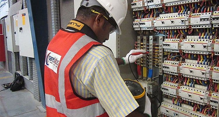
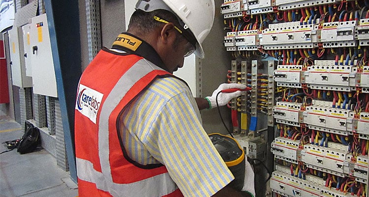
THIRD PARTY INSPECTION OF ELECTRICAL INSTALLATION
Carelabs is authorized provider of Electrical Installation’s Study, Analysis, Inspection, and Certification services in UAE, Middle East, Africa & Europe and provide Third Party Inspection of Electrical Installation.
A third-party inspection company is a business organization complying with the ISO 17020 standard. Third party inspection agencies are involved in inspection and testing. In simple words any other agency other than DEWA, SEWA or any other government agency, who conduct inspection, fall under third party inspection category.
An ‘Electrical installation’ according to the IEE Wiring Regulations, is ‘an Assembly of associated electrical equipment to fulfil a specific purpose and having certain Co-ordinated characteristics. Growing concern for public safety and the increasing complexity of today’s fixed electrical installations in domestic, commercial and industrial premises places extra responsibility on electrical test engineers who are charged with verifying conformity to today’s stringent international standard. Thus inspection of installations are done periodically and often nowadays.
Third Party Inspection Procedures are as Follows:
Testing an Electrical Installation
The visual inspection is first carried out to confirm that permanently wired electrical equipment is in compliance with the safety requirements and not visibly damaged, and that fire barriers, protective-, monitoring-, isolating and switching devices, and all relevant documentation are present. After this inspection, electrical testing may commence Other methods are not precluded provided they give equally valid results. Only with the appropriate experience and training, safe clothing, and the right test tools is a person considered competent to test installations. When testing is undertaken it should be ensured that adequate precautions are taken to avoid damage or injury to people, equipment or property, and ensured that unauthorized persons are kept away from danger.
Ring Final Circuit Continuity
The ring final circuit, feeding 13 A sockets, is extremely widely used, both in domestic and in commercial or industrial situations. It is very important that each of the three rings associated with each circuit (phase, neutral and protective conductors) should be continuous and not broken. If this happens, current will not be properly shared by the circuit conductors. Following are the steps for the test.
- Within the distribution board, remove the Line, the Neutral and the Earth conductors from its terminals. Since this is a ring circuit there will be two of each in the same terminal.
- Select the low reading ohm meter function and null the tester.
- Measure between Line to Line to get the reading for r1.
- Measure between Neutral to Neutral to get the reading for rn.
- Measure between Earth and Earth to get the reading for r2.
- Connect the first (outgoing) Line to the second (incoming) Earth and connect the second (incoming) Line to the first (outgoing) Earth (if you cannot see which one is the incoming or the outgoing conductor, just make guess, the testing will show whether you are correct or not).
- Using the low reading ohm meter, test between Line and Earth on every outlet on the ring circuit. The highest reading is the (R1+R2) for the circuit. The readings at each of the sockets wired on the ring should be very similar and the value should be according to this formula: (r1 +r2)/4. Every time the measured value is deviating by more than 0.5 ohms, the connection at the accessory terminals should be investigated.
- Remove the cross connection between the Line and Earth conductors and cross connect the Line and Neutral conductors instead (L1 to N2 and L2 to N1).
Insulation Resistance of Electrical Installation
Insulation integrity is critical to prevent electric shock and fire. It is generally measured between live conductors; and between each live conductor and earth. To measure the insulation resistance between live conductors and earth, the complete installation must be switched off, all lamps removed and all equipment disconnected. All fuses must be left in, circuit breakers closed and final circuit switches closed.
Basically, you’re applying a voltage (specifically a highly regulated, stabilized DC voltage) across a dielectric, measuring the amount of current (leakage current) flowing through that dielectric, and then calculating a resistance measurement. The resistance measurement is in Megohms. You use this resistance measurement to evaluate insulation integrity.
You can use it as:
- A quality control measure at the time a piece of electrical equipment is produced;
- An installation requirement to help ensure specifications are met and to verify proper hookup;
- A periodic preventive maintenance task; and
- A troubleshooting tool.
Connect two leads (positive and negative) across an insulation barrier. After making connections, apply the test voltage for 1 minute. During this interval, the resistance reading should drop or remain relatively steady. Larger insulation systems will show a steady decrease; smaller systems will remain steady because the capacitive and absorption currents drop to zero faster than on larger systems. After 1 minute, you should read and record the resistance value.
Protection by Separation of Circuits
The separation of the live parts from those of other circuits and from earth should be verified by a measurement of the insulation resistance. The resistance values obtained should be identical with the values mentioned previously with all appliances, as far as possible, connected.
Floor and Wall Resistance
If applicable, at least three floor and wall resistance measurements need to be made per location, one being approximately 1 meter from any accessible extraneous-conductive part in the location, with the remaining two measurements taken at greater distances. The series of measurements is repeated for each relevant surface of the location.
Measurement of the Earth Electrode Resistance
Measurement of the resistance of an earth electrode is made by an appropriate method, for example, using two auxiliary earth electrodes or ‘spikes’. Before testing, the earthing rod must be disconnected from the installation’s main earthing terminal. In doing this, the installation will consequently have no earth protection and therefore must be completely de-energized prior to testing. Earth resistance testing must not be carried out on a live system. One auxiliary electrode is placed at a set distance from the earth electrode, and the other at 62% of the distance between the two in a straight line. The test measures the earth resistance and also detects the voltage between the auxiliary electrodes, and if this exceeds 10 V, the test is inhibited
High Voltage Test (Dielectric Voltage-withstand Test)
High voltage test also known a Hipot test checks for good isolation. It makes sure no current will flow from one point to another point. Only electrically qualified workers may perform this testing.
Following are the steps to be carried out for Hipot test
- Connect the ground lead of the HIPOT Tester to a suitable building ground or grounding electrode conductor. Attach the high voltage lead to one of the isolated circuit phase conductors.
- Switch on the HIPOT Tester. Set the meter to 1000 Volts or pre decide DC Voltage. Push the “Test” button on the meter and after one minute observe the resistance reading. Record the reading for reference.
- At the end of the one minute test, switch the HIPOT Tester from the high potential test mode to the voltage measuring mode to confirm that the circuit phase conductor and voltage of HIPOT Tester are now reading zero volts.
- Repeat this test procedure for all circuit phase conductors testing each phase to ground and each phase to each phase.
- When testing is completed disconnect the HIPOT Tester from the circuits under test and confirm that the circuits are clear to be re-connected and re-energized.
- To PASS the unit or Cable under Test must be exposed to a minimum Stress of pre decide Voltage for 1 minute without any Indication of Breakdown. For Equipments with total area less than 0.1 m2, the insulation resistance shall not be less than 400 MΩ. For Equipment with total area larger than 0.1 m2 the measured insulation resistance times the area of the module shall not be less than 40 MΩ⋅m2 .
Earth Continuity Test
The Earth Continuity test is sometime referred to as the Earth Bond test or the Earth Resistance test. In effect they all measure that there is a good connection between the mains plug and the Earth point. This test is carried out on all Class I appliances. A good connection is defined as having a resistance of less than 0.1 ohms
This test is performed by measuring the resistance between the third pin (ground) and outside metal body of the product under test. The maximum acceptable value is generally 0.5 ohms although certain standards may specify 0.1 ohms. This test is generally carried out at a slightly higher current (25–60 A) so that the ground bond circuit maintains safe voltages on the chassis of the product, even at a high current, before the circuit breaker trips. This test is essential so that the product does not cause an electric shock resulting from insulation failure.
Checking for Protection Against Electric Shocks & Electric Fires
Protection against electric shock consists in providing provision for basic protection (protection against direct contact) with provision for fault protection (protection against indirect contact). Coordinated provisions result in a protective measure.
One of the most common protective measures consists in “automatic disconnection of supply” where the provision for fault protection consists in the implementation of a system earthing. Deep understanding of each standardized system (TT, TN and IT system) is necessary for a correct implementation. Electrical fires are caused by overloads, short circuits and earth leakage currents, but also by electric arcs in cables and connections. These dangerous electric arcs are not detected by residual current devices nor by circuit breakers or fuses. The arc fault detector technology makes it possible to detect dangerous arcs and thus provide additional protection of installations. See Arc Fault Detection Devices (AFDD) for more information.
LV Distribution
The system earthing is one protective measure commonly used for the protection against electric shocks. These systems earthings have a major impact on the LV electrical installation architecture and they need to be analysed as early as possible. Advantages and drawbacks are to be analysed for a correct selection.
Another aspect needing to be considered at the earlier stage is the external influences. In large electrical installation, different external influences may be encountered and need to be considered independently. As a result of these external influences proper selection of equipment according to their IP or IK codes has to be made.
Sizing and Protection of Conductors
Selection of cross-sectional-areas of cables or isolated conductors for line conductors is certainly one of the most important tasks of the design process of an electrical installation as this greatly influences the selection of over current protective devices, the voltage drop along these conductors and the estimation of the prospective short-circuit currents: the maximum value relates to the over current protection and the minimum value relates to the fault protection by automatic disconnection of supply. This has to be done for each circuit of the installation. Similar task is to be done for the neutral conductor and for the Protective Earth (PE) conductor. During an inspection, inspector have to check whether the dimension for this are precise or not.
Overvoltage Protection
Direct or indirect lightning strokes can damage electrical equipment at a distance of several kilometres. Operating voltage surges, transient and industrial frequency overvoltage can also produce the same consequences. All protective measures against overvoltage need to be installed. One of the most used corresponds to the use of Surge Protective Devices (SPD). Their selection; installation and protection within the electrical installation request some particular attention and need to be inspected.
Harmonics
Harmonic currents in the network affect the quality of energy and are at the origin of many disturbances as overloads, vibrations, ageing of equipment, trouble of sensitive equipment, of local area networks. Inspector need to check for the presence of harmonics.
After the inspection the third party agency is obliged to give a detailed report on the results of inspection conducted.
Periodic inspection and testing is necessary because all electrical installations deteriorate due to a number of factors such as damage, wear and tear, corrosion, excessive electrical loading, ageing and environmental influences. Electricity can be seen as an ‘invisible danger’ that can cause people to have shocks, burns or even death, as well as severe damage to properties, fires and explosions.
Get Started
Need expert support?
Carelabs delivers arc flash studies, power system analysis, and DEWA compliance services across the UAE.